wireguard-docs
API reference guide for WireGuard including Setup, Configuration, and Usage, with examples. All credit goes to the WireGuard project, [zx2c4](https://www.zx2c4.com/) and the [open source contributors](https://github.com/WireGuard/WireGuard/graphs/contributors) for the original software,
this is my solo unofficial attempt at providing more comprehensive documentation, API references, and examples. Source for these docs, example code, and issue tracker: [wireguard-docs](https://github.com/pirate/wireguard-docs) Nicer HTML page version: [docs.sweeting.me](https://docs.sweeting.me/s/wireguard)
WireGuard is an open-source VPN solution written in C by Jason Donenfeld and others, aiming to fix many of the problems that have plagued other modern server-to-server VPN offerings like IPSec/IKEv2, OpenVPN, or L2TP. It shares some similarities with other modern VPN offerings like Tinc and MeshBird, namely good cipher suites and minimal config. As of 2020-01 it’s been merged into the 5.6 version of the Linux kernel, meaning it will ship with most Linux systems out-of-the-box.
Official Links
WireGuard Goals
- strong, modern security by default
- minimal config and key management
- fast, both low-latency and high-bandwidth
- simple internals and small protocol surface area
- simple CLI and seamless integration with system networking
It's also fast as hell. I routinely get sub 0.5ms pings and 900mbps+ on good connections.
(See [this WireGuard topology write-up](https://www.ckn.io/blog/2017/11/14/wireguard-vpn-typical-setup/))
Table of Contents
See wireguard-docs for example code and documentation source.
- Table of Contents
- Intro
- WireGuard Documentation
- Further Reading
Intro
Whether living behind the Great Wall of China or just trying to form a network between your servers, WireGuard is a great option and serves as a “lego block” for building networks (much in the same way that ZFS is a lego block for building filesystems).
WireGuard Overview
- minimal config, low tunable surface area and sane defaults
- minimal key management work needed, just 1 public & 1 private key per host
- behaves like a normal network interface, behaves well with standard kernel packet routing rules
- ability to easily create a LAN like 192.0.2.0/24 between all servers, or more complex networks using custom routes
- ability to route some traffic or all traffic to/through arbitrary hosts on the VPN LAN
- robust automatic reconnects after reboots / network downtime / NAT connection table drops
- fast (low latency and line-rate bandwidth)
- modern encryption, secure by default with forward secrecy & resilience to downgrade attacks
- supports normal IP traffic, including ICMP, not just TCP/HTTP
- ability to join the VPN from Ubuntu, FreeBSD, iOS, macOS, Windows, Android, and some Chromebooks (via apps or native clients)
- supports both running on the host routing traffic for docker or running in a docker container routing for the host
Things WireGuard does not do:
- form a self-healing mesh network where nodes automatically gossip with neighbors
- include its own signalling/discovery layer for double-NAT traversal (WebRTC-style)
- handle automatically distributing & revoking keys through a central authority
- allow sending raw layer-2 ethernet frames (it’s at the IP layer)
But you can write your own solutions for these problems using WireGuard under the hood (like Tailscale or AltheaNet).
List of Other VPN Solutions
- WireGuard
- IPSec (IKEv2)/strongSwan: in my experience, there was lots of brittle config that was different for each OS, the NAT busting setup is very manual and involves updating the central server and starting all the others in the correct order, it wasn’t great at becoming stable again after network downtime, had to be manually restarted often. your mileage may vary.
- OpenVPN: can work over UDP or be disguised as HTTPS traffic over TCP
- StealthVPN: haven’t tried it, should I?
- DsVPN: I think it does TCP-over-TCP which usually doesn’t end well…
- SoftEther (SSTP): haven’t tried it yet, should I? (also does TCP-over-TCP?)
- L2TP: somewhat outdated
- PPTP: ancient, inflexible, insecure, doesn’t solve all the requirements
- SOCKS/SSH: good for proxying single-port traffic, not a full networking tunnel or VPN
Mesh VPN Solutions
- TINC: haven’t tried it yet, but it doesn’t work on iOS, worst case scenario I could live
- VPNCloud: similar properties to WireGuard, with more auto-mesh features
- cjdns: haven’t tried it yet, should I?
- ZeroTier: haven’t tried it yet, should I?
- MeshBird: “Cloud native” VPN/networking layer
- Yggdrasil Network: Yggdrasil is a self-arranging IPv4/IPv6 mesh VPN (haven’t tried it yet)
VPN Setup Tools
- Algo WireGuard setup tool
- Streisand Multi-protocol setup tool
- IKEv2-setup IKEv2 server setup script
- WireGuard-Manager WireGuard setup tool, all in one
WireGuard Documentation
Glossary
Example Strings
These are demo hostnames, domain names, IP addresses, and ranges used in the documentation and example configs. Replace them with your preferred values when doing your own setup.
- Example domain:
example-vpn.devcan be replaced with any publicly accessible domain you control - Example hostnames:
public-server1,public-server2,home-server,laptop,phonecan be changed to your device hostnames - IP addresses & ranges:
192.0.2.1/24,192.0.2.3,192.0.2.3/32,2001:DB8::/64can be replaced with your preferred subnets and addresses (e.g.192.168.5.1/24)
Wherever you see these strings below, they’re just being used as placeholder values to illustrate an example and have no special meaning.
Make sure to change the IP addresses in your configs! The blocks used in these docs are reserved for example purposes by the IETF and should never be used in real network setups.
You can use any private range you want for your own setups, e.g. 10.0.44.0/24, just make sure
they don’t conflict with any of the LAN subnet ranges your peers are on.
Peer/Node/Device
A host that connects to the VPN and registers a VPN subnet address such as 192.0.2.3 for itself. It can also optionally route traffic for more than its own address(es) by specifying subnet ranges in comma-separated CIDR notation.
Bounce Server
A publicly reachable peer/node that serves as a fallback to relay traffic for other VPN peers behind NATs. A bounce server is not a special type of server, it’s a normal peer just like all the others, the only difference is that it has a public IP and has kernel-level IP forwarding turned on which allows it to bounce traffic back down the VPN to other clients.
See more: How NAT traversal works (Tailscale uses WireGuard under the hood)
Subnet
A group of IPs separate from the public internet, e.g. 192.0.2.1-255 or 192.168.1.1/24. Generally behind a NAT provided by a router, e.g. in office internet LAN or a home Wi-Fi network.
CIDR Notation
A way of defining a subnet and its size with a “mask”, a smaller mask = more address bits usable by the subnet & more IPs in the range. Most common ones:
192.0.2.1/32(a single IP address,192.0.2.1) netmask =255.255.255.255192.0.2.1/24(256 addresses from192.0.2.0-192.0.2.255) netmask =255.255.255.0192.0.2.1/16(65,536 IPs from192.0.0.0-192.0.255.255) netmask =255.255.0.0192.0.2.1/8(16,777,216 IPs from192.0.0.0-192.255.255.255) netmask =255.0.0.00.0.0.0/0(4,294,967,296 addresses from0.0.0.0-255.255.255.255) netmask =0.0.0.0- IPv6 CIDR notation is also supported e.g.
2001:DB8::/64
Classless Inter-Domain Routing (CIDR)
To people just getting started 192.0.2.1/32 may seem like a weird and confusing way to refer to a single IP. This design is nice though because it allows peers to expose multiple IPs if needed without needing multiple notations. Just know that anywhere you see something like 192.0.2.3/32, it really just means 192.0.2.3.
NAT
A subnet with private IPs provided by a router standing in front of them doing Network Address Translation, individual nodes are not publicly accessible from the internet, instead the router keeps track of outgoing connections and forwards responses to the correct internal IP (e.g. standard office networks, home Wi-Fi networks, free public Wi-Fi networks, etc)
Public Endpoint
The publicly accessible address:port for a node, e.g. 123.124.125.126:1234 or some.domain.tld:1234 (must be accessible via the public internet, generally can’t be a private IP like 10.0.0.1 or 192.168.1.1 unless it’s directly accessible using that address by other peers on the same subnet).
Private key
A WireGuard private key for a single node, generated with:
wg genkey > example.key
(never leaves the node it’s generated on)
Public key
A WireGuard public key for a single node, generated with:
wg pubkey < example.key > example.key.pub
(shared with other peers)
DNS
Domain Name Server, used to resolve hostnames to IPs for VPN clients, instead of allowing DNS requests to leak outside the VPN and reveal traffic. Leaks are testable with dnsleak.com.
How WireGuard Works
How Public Relay Servers Work
Public relays are just normal VPN peers that are able to act as an intermediate relay server between any VPN clients behind NATs, they can forward any VPN subnet traffic they receive to the correct peer at the system level (WireGuard doesn’t care how this happens, it’s handled by kernel IP forwarding plus whatever firewall/NAT rules your host needs).
If all peers are publicly accessible, you don’t have to worry about special treatment to make one of them a relay server, it’s only needed if you have any peers connecting from behind a NAT.
Each client only needs to define the publicly accessible servers/peers in its config, any traffic bound to other peers behind NATs will go to the catchall VPN subnet (e.g. 192.0.2.1/24) in the public relays AllowedIPs route and will be forwarded accordingly once it hits the relay server.
In summary: only direct connections between clients should be configured, any connections that need to be bounced should not be defined as peers, as they should head to the bounce server first and be routed from there back down the VPN to the correct client.
Important: traffic bounced through a relay server is not end-to-end encrypted between the two NAT-ed peers. The relay server decrypts incoming traffic from one peer and re-encrypts it with the destination peer’s key before forwarding. This means the relay server can see the plaintext VPN traffic passing through it. Each hop (A↔Relay, Relay↔B) is independently encrypted, but the relay acts as a trusted intermediary that performs Cryptokey Routing to match the decrypted packet’s destination IP to the correct peer. For more details, see the WireGuard whitepaper and Pro Custodibus’s explanation of hub-and-spoke E2EE limitations. If end-to-end encryption between NAT-ed peers is required, consider using an application-level encryption layer (e.g. TLS) on top of WireGuard, or a solution like Tailscale’s DERP relays which forward opaque encrypted packets without decrypting them.
How WireGuard Routes Packets
More complex topologies are definitely achievable, but these are the basic routing methods used in typical WireGuard setups:
- Direct node-to-node
In the simplest case, the nodes will either be on the same LAN or both be publicly accessible. Define directly accessible nodes with hardcodedEndpointaddresses and ports so that WireGuard can connect straight to the open port and route UDP packets without intermediate hops. - Node behind local NAT to public node
When 1 of the 2 parties is behind remote NAT (e.g. when a laptop behind NAT connects topublic-server2), define the publicly accessible node with a hardcodedEndpointand the NAT-ed node without. The connection will be opened from NAT client -> public client, then traffic will route directly between them in both directions as long as the connection is kept alive by outgoingPersistentKeepalivepackets from the NAT-ed client. - Node behind local NAT to node behind remote NAT (via relay)
Most of the time when both parties are behind NATs, the NATs do source port randomization making direct connections infeasible, so they will both have to open a connection topublic-server1, and traffic will forward through the intermediary bounce server as long as the connections are kept alive. - Node behind local NAT to node behind remote NAT (via UDP NAT hole-punching)
While sometimes possible, it’s generally infeasible to do direct NAT-to-NAT connections on modern networks, because many NAT routers randomize source ports or otherwise restrict unsolicited return traffic. A more advanced solution needs some external signaling/discovery component to tell each side what public IP:port tuple the other side currently appears to have, and even then success still depends on the NAT behavior of both networks. This is roughly the role played by STUN/ICE-style tooling in systems like WebRTC, but plain WireGuard does not include that machinery by itself. See the full section below on NAT to NAT Connections for more information.
More specific (also usually more direct) routes provided by other peers will take precedence when available, otherwise traffic will fall back to the least specific route and use the 192.0.2.1/24 catchall to forward traffic to the bounce server, where it will in turn be routed by the relay server’s system routing table (net.ipv4.ip_forward = 1) back down the VPN to the specific peer that’s accepting routes for that traffic. WireGuard does not automatically find the fastest route or attempt to form direct connections between peers if not already defined, it just goes from the most specific route in [Peers] to least specific.
You can figure out which routing method WireGuard is using for a given address by measuring the ping times to figure out the unique length of each hop, and by inspecting the output of:
wg show wg0
What WireGuard Traffic Looks Like
WireGuard uses encrypted UDP packets for all traffic, it does not provide guarantees around packet delivery or ordering, as that is handled by TCP connections within the encrypted tunnel.

Further reading:
- https://www.wireshark.org/docs/dfref/w/wg.html
- https://github.com/Lekensteyn/wireguard-dissector
- https://nbsoftsolutions.com/blog/viewing-wireguard-traffic-with-tcpdump
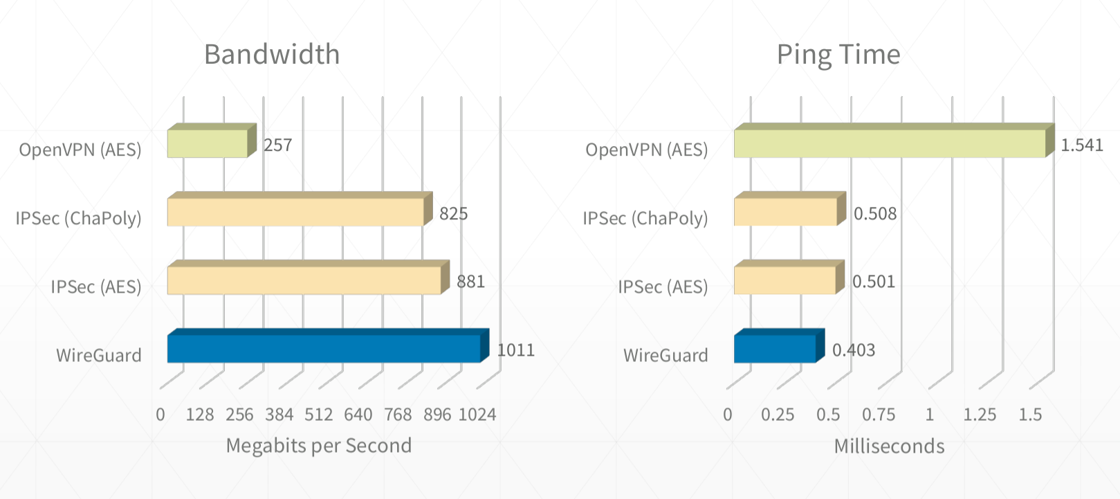
WireGuard Performance
WireGuard claims faster performance than most other competing VPN solutions, though the exact numbers are sometimes debated and may depend on whether hardware-level acceleration is available for certain cryptographic ciphers.
WireGuard’s performance gains are achieved by handling routing at the kernel level, and by using modern cipher suites running on all cores to encrypt traffic. WireGuard also gains a significant advantage by using UDP with no delivery/ordering guarantees (compared to VPNs that run over TCP or implement their own guaranteed delivery mechanisms).

Further reading:
- https://www.wireguard.com/performance/
- https://www.reddit.com/r/linux/comments/9bnowo/wireguard_benchmark_between_two_servers_with_10/
- https://restoreprivacy.com/openvpn-ipsec-wireguard-l2tp-ikev2-protocols/
WireGuard Security Model
WireGuard uses the following protocols and primitives to secure traffic:
- ChaCha20 for symmetric encryption, authenticated with Poly1305, using RFC7539’s AEAD construction
- Curve25519 for ECDH
- BLAKE2s for hashing and keyed hashing, described in RFC7693
- SipHash24 for hashtable keys
- HKDF for key derivation, as described in RFC5869
WireGuard’s cryptography is essentially an instantiation of Trevor Perrin’s Noise framework. It’s modern and, again, simple. Every other VPN option is a mess of negotiation and handshaking and complicated state machines. WireGuard is like the Signal/Axolotl of VPNs, except it’s much simpler and easier to reason about (cryptographically, in this case) than double ratchet messaging protocols. It is basically the qmail of VPN software. And it’s ~4000 lines of code. It is plural orders of magnitude smaller than its competitors.
https://news.ycombinator.com/item?id=14599834
Further reading:
- https://www.wireguard.com/papers/wireguard.pdf
- https://eprint.iacr.org/2018/080.pdf
- https://courses.csail.mit.edu/6.857/2018/project/He-Xu-Xu-WireGuard.pdf
- https://www.wireguard.com/talks/blackhat2018-slides.pdf
- https://arstechnica.com/gadgets/2018/08/wireguard-vpn-review-fast-connections-amaze-but-windows-support-needs-to-happen/
How WireGuard Manages Keys
Authentication in both directions is achieved with a simple public/private key pair for each peer. Each peer generates these keys during the setup phase, and shares only the public key with other peers.
No other certificates or pre-shared keys are needed beyond the public/private keys for each node.
Key generation, distribution, and revocation can be handled in larger deployments using a separate service like Ansible or Kubernetes Secrets.
Some services that help with key distribution and deployment:
- https://pypi.org/project/wireguard-p2p/
- https://github.com/trailofbits/algo
- https://github.com/StreisandEffect/streisand
- https://github.com/its0x08/wg-install
- https://github.com/brittson/wireguard_config_maker
- https://www.wireguardconfig.com
- https://github.com/UrielCh/wireguard
You can also read in keys from a file or via command if you don’t want to hardcode them in wg0.conf, this makes managing keys via 3rd party service much easier:
[Interface]
...
PreUp = wg set %i private-key <(cat /some/path/%i/privkey)
Multiple servers should not share the same private key. WireGuard’s protocol assumes distinct peers use distinct private keys, and reusing one can cause replay-related problems and involuntary endpoint roaming between those machines. See the WireGuard whitepaper discussion of timestamp/replay behavior. Most of the time, every peer should have its own public/private keypair so that peers can be individually identified and revoked.
Usage
QuickStart
Overview of the general process:
- Install
apt install wireguardorpkg/brew install wireguard-toolson each node - Generate public and private keys locally on each node
wg genkey+wg pubkey - Create a
wg0.confWireGuard config file on the main relay server[Interface]Make sure to specify the local tunnel address(es) the server will use, e.g.Address = 192.0.2.1/24,2001:DB8::1/64for a dual-stack VPN subnet[Peer]Create a peer section for every client joining the VPN, using their corresponding remote public keys
- Create a
wg0.confon each client node[Interface]Make sure to specify only the client peer’s own tunnel IPs when it doesn’t relay traffic, e.g.Address = 192.0.2.3/32,2001:DB8::3/128.[Peer]Create a peer section for each public peer not behind a NAT, and make sure to use IPv4 and/or IPv6 CIDRs as appropriate when defining what should route through that peer, e.g. relay serverAllowedIPs = 192.0.2.0/24,2001:DB8::/64or simple clientAllowedIPs = 192.0.2.3/32,2001:DB8::3/128.
- Start WireGuard on the main relay server with
wg-quick up /full/path/to/wg0.conf - Start WireGuard on all the client peers with
wg-quick up /full/path/to/wg0.conf - Traffic is routed from peer to peer using most specific route first over the WireGuard interface, e.g.
ping 192.0.2.3checks for a direct route to a peer withAllowedIPs = 192.0.2.3/32first, then falls back to a relay server that’s accepting IPs in the whole subnet
Setup
# install on Ubuntu
sudo apt install wireguard

# install on macOS
brew install wireguard-tools

# install on FreeBSD
pkg install wireguard

# install on iOS/Android using Apple App Store/Google Play Store
# install on other systems using https://www.wireguard.com/install/#installation
ChromeOS note: some Chromebooks have basic built-in WireGuard support in the VPN settings UI, where you can add a connection and select Provider type: WireGuard. ChromeOS also documents VPN.Type = WireGuard in its ONC format for managed or imported network configs. Under the hood, ChromiumOS implements this as a built-in WireGuard client backed by the kernel module and documents a kernel 5.4+ requirement. See Google’s Chromebook VPN setup guide, the Chromium ONC spec, and the ChromiumOS VPN implementation notes.
# to enable kernel forwarding on bounce servers
echo "net.ipv4.ip_forward = 1" | sudo tee -a /etc/sysctl.conf
echo "net.ipv6.conf.all.forwarding = 1" | sudo tee -a /etc/sysctl.conf
# optional IPv4-specific proxy_arp example for proxy-ARP based topologies
echo "net.ipv4.conf.all.proxy_arp = 1" | sudo tee -a /etc/sysctl.conf
sudo sysctl -p /etc/sysctl.conf

# to add IPv4 forwarding/NAT rules on bounce servers
sudo iptables -A INPUT -m conntrack --ctstate RELATED,ESTABLISHED -j ACCEPT
sudo iptables -A FORWARD -m conntrack --ctstate RELATED,ESTABLISHED -j ACCEPT
sudo iptables -A FORWARD -i wg0 -o wg0 -m conntrack --ctstate NEW -j ACCEPT
sudo iptables -t nat -A POSTROUTING -s 192.0.2.0/24 -o eth0 -j MASQUERADE

# to add IPv6 forwarding rules on bounce servers
sudo ip6tables -A INPUT -m conntrack --ctstate RELATED,ESTABLISHED -j ACCEPT
sudo ip6tables -A FORWARD -m conntrack --ctstate RELATED,ESTABLISHED -j ACCEPT
sudo ip6tables -A FORWARD -i wg0 -o wg0 -m conntrack --ctstate NEW -j ACCEPT
# optional NAT66 example if you intentionally want IPv6 masquerading
# sudo ip6tables -t nat -A POSTROUTING -s 2001:DB8::/64 -o eth0 -j MASQUERADE
Config Creation
nano wg0.conf # can be placed anywhere as long as the filename matches the interface name (often /etc/wireguard/wg0.conf)
Key Generation
# generate private key
wg genkey > example.key

# generate public key
wg pubkey < example.key > example.key.pub
Start / Stop
wg-quick up /full/path/to/wg0.conf
wg-quick down /full/path/to/wg0.conf
# Note: CONFIG_FILE can be in any directory, but its filename must still match the interface name, e.g. ./wg0.conf or /full/path/to/wg0.conf
# If wg0.conf is in /etc/wireguard you can use the simpler:
wg-quick up wg0
# start/stop VPN network interface
ip link set wg0 up
ip link set wg0 down

# register/unregister VPN network interface
ip link add dev wg0 type wireguard
ip link delete dev wg0

# register/unregister local VPN address
ip address add dev wg0 192.0.2.3/32
ip address delete dev wg0 192.0.2.3/32

# register/unregister VPN route
ip route add 192.0.2.3/32 dev wg0
ip route delete 192.0.2.3/32 dev wg0
Inspect
Interfaces
# show system LAN and WAN network interfaces
ip address show
# or if ip is not available:
ifconfig

# show system VPN network interfaces
ip link show wg0
# or
ifconfig wg0

# show WireGuard VPN interfaces
wg show all
wg show wg0
Addresses
# show public IP address
ip address show eth0
# or
ifconfig eth0
# or
dig -4 +short myip.opendns.com @resolver1.opendns.com

# show VPN IP address
ip address show wg0
Routes
# show WireGuard routing table and peer connections
wg show
wg show wg0 allowed-ips

# show system routing table
ip route show table main
ip route show table local

# show system route to specific address
ip route get 192.0.2.3
Logs
To enable additional logging run:
modprobe wireguard
echo module wireguard +p > /sys/kernel/debug/dynamic_debug/control
To follow logs:
dmesg -wH
Testing
Ping Speed
# check that the main relay server is accessible directly via public internet
ping public-server1.example-vpn.dev

# check that the main relay server is available via VPN
ping 192.0.2.1

# check that public peers are available via VPN
ping 192.0.2.2

# check that remote NAT-ed peers are available via VPN
ping 192.0.2.3

# check that NAT-ed peers in your local LAN are available via VPN
ping 192.0.2.4
Bandwidth
# install iperf using your preferred package manager
apt/brew/pkg/opkg install iperf

# check bandwidth over public internet to relay server
iperf -s # on public relay server
iperf -c public-server1.example-vpn.dev # on local client

# check bandwidth over VPN to relay server
iperf -s # on public relay server
iperf -c 192.0.2.1 # on local client

# check bandwidth over VPN to remote public peer
iperf -s # on remote public peer
iperf -c 192.0.2.2 # on local client

# check bandwidth over VPN to remote NAT-ed peer
iperf -s # on remote NAT-ed peer
iperf -c 192.0.2.3 # on local client

# check bandwidth over VPN to local NAT-ed peer (on same LAN)
iperf -s # on local NAT-ed peer
iperf -c 192.0.2.4 # on local client
DNS
Check for DNS leaks using dnsleak.com, or by checking the resolver on a lookup:
dig example.com A
Config Reference
Overview
WireGuard config is in INI syntax, defined in a file usually called wg0.conf. It can be placed anywhere on the system, but is often placed in /etc/wireguard/wg0.conf.
The config path is specified as an argument when running any wg-quick command, e.g:
wg-quick up /etc/wireguard/wg0.conf
The config file name must be in the format ${name of the new WireGuard interface}.conf. WireGuard interface names are typically prefixed with wg and numbered starting at 0, but you can use any name that matches the regex ^[a-zA-Z0-9_=+.-]{1,15}$.
Config files can opt to use the limited set of wg config options, or the more extended wg-quick options, depending on what command is preferred to start WireGuard. These docs recommend sticking to wg-quick as it provides a more powerful and user-friendly config experience.
The core wg(8) config format covers peer/session state such as PrivateKey, ListenPort, FwMark, PublicKey, PresharedKey, AllowedIPs, Endpoint, and PersistentKeepalive. The convenience keys Address, DNS, Table, MTU, PreUp, PostUp, PreDown, and PostDown below are wg-quick(8) extensions. See wg(8) and wg-quick(8).
Jump to definition:
¶ [Interface]
¶ # Name = node1.example.tld
¶ Address = 192.0.2.3/32 (wg-quick only)
¶ ListenPort = 51820
¶ PrivateKey = localPrivateKeyAbcAbcAbc=
¶ DNS = 1.1.1.1,8.8.8.8 (wg-quick only)
¶ Table = 12345 (wg-quick only)
¶ MTU = 1420 (wg-quick only)
¶ PreUp = /bin/example arg1 arg2 %i (wg-quick only)
¶ PostUp = /bin/example arg1 arg2 %i (wg-quick only)
¶ PreDown = /bin/example arg1 arg2 %i (wg-quick only)
¶ PostDown = /bin/example arg1 arg2 %i (wg-quick only)
¶ [Peer]
¶ # Name = node2-node.example.tld
¶ AllowedIPs = 192.0.2.1/24
¶ Endpoint = node1.example.tld:51820
¶ PublicKey = remotePublicKeyAbcAbcAbc=
¶ PersistentKeepalive = 25
[Interface]
Defines the VPN settings for the local node.
Examples
- Node is a client that only routes traffic for itself and only exposes one IP
[Interface] # Name = phone.example-vpn.dev Address = 192.0.2.5/32 PrivateKey = <private key for phone.example-vpn.dev> - Node is a public bounce server that can relay traffic to other peers and exposes route for entire VPN subnet
[Interface]
# Name = public-server1.example-vpn.tld
Address = 192.0.2.1/24
ListenPort = 51820
PrivateKey = <private key for public-server1.example-vpn.tld>
DNS = 1.1.1.1
# Name
This is just a standard comment in INI syntax used to help keep track of which config section belongs to which node, it’s completely ignored by WireGuard and has no effect on VPN behavior.
NOTE: All comments, including # Name, are removed from the .conf files by certain operations and applications.
If you need to identify peers, consider using a wireguard vanity key generator, such as
wireguard-vanity-keygen or
wireguard-vanity-address,
which will allow you to include the host name in the public key of the host.
The key generation can take minutes (4 characters), hours (5 characters) or longer,
so consider using an abbreviation for hosts with longer names.
Address
Defines what address(es) the local WireGuard interface should use. Depending on whether the node is a simple client joining the VPN subnet, or a bounce server that’s relaying traffic between multiple clients, this can be set to a single IP of the node itself (specified with CIDR notation), e.g. 192.0.2.3/32 or 2001:DB8::3/128, or to multiple IPv4/IPv6 addresses on the same interface.
Examples
-
Node is a client that only routes traffic for itself
Address = 192.0.2.3/32 -
IPv6-only client address:
Address = 2001:DB8::3/128 -
Node is a public bounce server that can relay traffic to other peers
When the node is acting as the public bounce server, it should use an address inside the VPN subnet together with the subnet prefix length it routes, not just a/32for itself.
Address = 192.0.2.1/24
- Dual-stack example with both IPv4 and IPv6:
Address = 192.0.2.1/24,2001:DB8::1/64
ListenPort
When the node is acting as a public bounce server, it should hardcode a port to listen for incoming VPN connections from the public internet. Clients that are not acting as relays usually do not need to set this value, but they still can if they want a fixed local UDP port.
Examples
- Using default WireGuard port
ListenPort = 51820 - Using custom WireGuard port
ListenPort = 7000
PrivateKey
This is the private key for the local node, never shared with other servers. All nodes must have a private key set, regardless of whether they are public bounce servers relaying traffic, or simple clients joining the VPN.
This key can be generated with wg genkey > example.key
Examples
PrivateKey = somePrivateKeyAbcdAbcdAbcdAbcd=
DNS
This is a wg-quick convenience option for the local machine, not a WireGuard setting that is announced or pushed to peers. In wg-quick, IP entries are applied as DNS servers for the local interface via resolvconf, and non-IP entries are treated as DNS search domains. See wg-quick(8) and the WireGuard for Windows parser.
Examples
- The value can be left unconfigured to use the system’s default DNS handling
- A single DNS server can be provided:
DNS = 1.1.1.1 - Multiple DNS servers can be provided:
DNS = 1.1.1.1,8.8.8.8 - A DNS server and search domain can be provided:
DNS = 10.0.0.2, internal.example.com
Table
Optionally defines which routing table to use for the WireGuard routes, not necessary to configure for most setups.
There are two special values: ‘off’ disables the creation of routes altogether, and ‘auto’ (the default) adds routes to the default table and enables special handling of default routes.
See wg-quick(8).
Examples
Table = 1234
MTU
Optionally defines the maximum transmission unit (MTU, aka packet/frame size) to use when connecting to the peer, not necessary to configure for most setups.
The MTU is automatically determined from the endpoint addresses or the system default route, which is usually a sane choice.
You should avoid setting this if at all possible. You almost certainly do not want 1500 here due to the encapsulation overhead.
See wg-quick(8).
Examples
MTU = 1420
PreUp
Optionally run a command before the interface is brought up. This option can be specified multiple times, with commands executed in the order they appear in the file.
Examples
- Add an IP route
PreUp = ip rule add ipproto tcp dport 22 table 1234
PostUp
Optionally run a command after the interface is brought up. This option can appear multiple times, as with PreUp
Examples
-
Read in a config value from a file or some command’s output
PostUp = wg set %i private-key <(some command here) -
Log a line to a file
PostUp = echo "$(date +%s) WireGuard Started" >> /var/log/wireguard.log -
Hit a webhook on another server
PostUp = curl https://events.example.dev/wireguard/started/?key=abcdefg -
Add a route to the system routing table
PostUp = ip rule add ipproto tcp dport 22 table 1234 -
Add an iptables rule to enable packet forwarding on the WireGuard interface
PostUp = iptables -A FORWARD -i %i -j ACCEPT; iptables -A FORWARD -o %i -j ACCEPT; iptables -t nat -A POSTROUTING -o eth0 -j MASQUERADE -
Configure
systemd-resolvedDNS settings for this interfacePostUp = resolvectl domain %i "~."; resolvectl dns %i 192.0.2.1; resolvectl dnssec %i yes
PreDown
Optionally run a command before the interface is brought down. This option can appear multiple times, as with PreUp
Examples
-
Log a line to a file
PreDown = echo "$(date +%s) WireGuard Going Down" >> /var/log/wireguard.log -
Hit a webhook on another server
PreDown = curl https://events.example.dev/wireguard/stopping/?key=abcdefg
PostDown
Optionally run a command after the interface is brought down. This option can appear multiple times, as with PreUp
Examples
-
Log a line to a file
PostDown = echo "$(date +%s) WireGuard Stopped" >> /var/log/wireguard.log -
Hit a webhook on another server
PostDown = curl https://events.example.dev/wireguard/stopped/?key=abcdefg -
Remove the iptables rule that forwards packets on the WireGuard interface
PostDown = iptables -D FORWARD -i %i -j ACCEPT; iptables -D FORWARD -o %i -j ACCEPT; iptables -t nat -D POSTROUTING -o eth0 -j MASQUERADE
[Peer]
Defines the VPN settings for a remote peer capable of routing traffic for one or more addresses (itself and/or other peers). Peers can be either a public bounce server that relays traffic to other peers, or a directly accessible client via LAN/internet that is not behind a NAT and only routes traffic for itself.
In the simple relay topology used throughout this README, all clients are defined as peers on the public bounce server. Simple clients that only route traffic for themselves only need to define peers for the public relay and any other nodes that are directly reachable. Nodes behind separate NATs are usually not defined as peers of each other in this topology, because traffic between them is expected to go through the public relay instead. In that setup, NAT-ed nodes point their relay peer at a broader subnet such as AllowedIPs = 192.0.2.1/24 on the public server. Traffic destined for a NAT-ed peer that is not directly defined will match the relay server’s broad AllowedIPs range, be encrypted to the relay server, and then be decrypted and re-encrypted by the relay for delivery to the final destination peer (see the security note above about relay traffic not being end-to-end encrypted).
In summary, all nodes must be defined on the main bounce server. On client nodes, only peers that are directly accessible from a node should be defined as peers of that node, and any peers that must be relayed by a bounce server should be left out and handled by the relay server’s catchall route.
In the configuration outlined in the docs below, a single server public-server1 acts as the relay bounce server for a mix of publicly accessible and NAT-ed clients, and peers are configured on each node accordingly:
-
in
public-server1wg0.conf(bounce server)
[peer]list:public-server2,home-server,laptop,phone -
in
public-server2wg0.conf(simple public client)
[peer]list:public-server1 -
in
home-serverwg0.conf(simple client behind NAT)
[peer]list:public-server1,public-server2 -
in
laptopwg0.conf(simple client behind NAT)
[peer]list:public-server1,public-server2 -
in
phonewg0.conf(simple client behind NAT)
[peer]list:public-server1,public-server2
Examples
- Peer is a simple public client that only routes traffic for itself
[Peer] # Name = public-server2.example-vpn.dev Endpoint = public-server2.example-vpn.dev:51820 PublicKey = <public key for public-server2.example-vpn.dev> AllowedIPs = 192.0.2.2/32 - Peer is a simple client behind a NAT that only routes traffic for itself
[Peer] # Name = home-server.example-vpn.dev PublicKey = <public key for home-server.example-vpn.dev> AllowedIPs = 192.0.2.3/32 - Peer is a public bounce server that can relay traffic to other peers
[Peer]
# Name = public-server1.example-vpn.tld
Endpoint = public-server1.example-vpn.tld:51820
PublicKey = <public key for public-server1.example-vpn.tld>
# routes traffic to itself and entire subnet of peers as bounce server
AllowedIPs = 192.0.2.1/24
PersistentKeepalive = 25
# Name
This is just a standard comment in INI syntax used to help keep track of which config section belongs to which node, it’s completely ignored by WireGuard and has no effect on VPN behavior.
Endpoint
Defines the publicly accessible address for a remote peer. This should be left out for peers behind a NAT or peers that don’t have a stable publicly accessible IP:PORT pair. Typically, this only needs to be defined on the main bounce server, but it can also be defined on other public nodes with stable IPs like public-server2 in the example config below. IPv6 literal endpoints are supported, but they must be wrapped in square brackets. After a packet is received from a peer, WireGuard also updates the stored endpoint to that peer’s most recent authenticated source IP:PORT.
Examples
- Endpoint is an IP address
Endpoint = 123.124.125.126:51820(IPv6 is also supported) - Endpoint is an IPv6 address:
Endpoint = [2001:DB8::1]:51820 - Endpoint is a hostname/FQDN
Endpoint = public-server1.example-vpn.tld:51820
AllowedIPs
This defines which IP prefixes the local node associates with a peer in WireGuard’s cryptokey routing table. When sending, the local node uses the destination IP to choose which peer to encrypt to. When receiving, it only accepts a decrypted packet from that peer if the packet’s source IP matches one of that peer’s AllowedIPs. This mapping is local to the machine that owns the config; it is not dynamically advertised to other peers. See WireGuard’s cryptokey routing overview and the WireGuard whitepaper.
On simple clients, this is usually a single address (the VPN address of the peer itself) or a small routed prefix. On bounce servers, this may be a broader range of IPs or subnets that should be routed back to that peer. Multiple IPs and subnets may be specified using comma-separated IPv4 or IPv6 CIDR notation (from a single /32 or /128 address, all the way up to 0.0.0.0/0 and ::/0 to indicate a default route to send all internet and VPN traffic through that peer). If you need “internet passthrough but no peer-to-peer access”, treat AllowedIPs as address mapping and source validation, and enforce any additional forwarding policy separately on the machine that would route the traffic.
When deciding how to route a packet, the system chooses the most specific route first, and falls back to broader routes. So for a packet destined to 192.0.2.3, the system would first look for a peer configured with 192.0.2.3/32 specifically, and would fall back to a peer configured with 192.0.2.1/24 or a larger range like 0.0.0.0/0 as a last resort.
Examples
-
peer is a simple client that only represents its own tunnel IP:
AllowedIPs = 192.0.2.3/32 -
peer is a simple client with an IPv6 tunnel address:
AllowedIPs = 2001:DB8::3/128 -
peer is a relay server that can bounce VPN traffic to all other peers
AllowedIPs = 192.0.2.1/24 -
peer is a relay server for a dual-stack VPN subnet:
AllowedIPs = 192.0.2.0/24,2001:DB8::/64 -
peer is a relay server that bounces all internet & VPN traffic (like a proxy), including IPv6
AllowedIPs = 0.0.0.0/0,::/0 -
peer is a relay server that routes to itself and only one other peer
AllowedIPs = 192.0.2.3/32,192.0.2.4/32 -
peer is a relay server that routes to itself and all nodes on its local LAN
AllowedIPs = 192.0.2.3/32,192.168.1.1/24
PublicKey
This is the public key for the remote node, shareable with all peers. All nodes must have a public key set, regardless of whether they are public bounce servers relaying traffic, or simple clients joining the VPN.
This key can be generated with wg pubkey < example.key > example.key.pub.
(see above for how to generate the private key example.key)
Examples
PublicKey = somePublicKeyAbcdAbcdAbcdAbcd=
PersistentKeepalive
If the connection is going from a NAT-ed peer to a public peer, the node behind the NAT must regularly send an outgoing keepalive packet in order to keep the bidirectional connection alive in the NAT router’s connection table.
Examples
-
local public node to remote public node
This value should be left undefined as persistent pings are not needed. -
local public node to remote NAT-ed node
This value should be left undefined as it’s the client’s responsibility to keep the connection alive because the server cannot reopen a dead connection to the client if it times out. -
local NAT-ed node to remote public node
PersistentKeepalive = 25this will send an authenticated empty keepalive packet every 25 seconds, keeping the connection open in the local NAT router’s connection table.
Advanced Topics
IPv6
The examples in these docs primarily use IPv4, but WireGuard is layer-3 only and natively supports both IPv4 and IPv6, including v4-in-v6 and v6-in-v4. In practice, the important patterns are:
Addressaccepts IPv6 interface addresses such as2001:DB8::3/128AllowedIPsaccepts IPv6 CIDRs such as2001:DB8::/64and the IPv6 default route::/0Endpointaccepts IPv6 literals, but they must be wrapped in square brackets, e.g.[2001:DB8::1]:51820- the
proxy_arpline shown in the Setup section is IPv4-specific; IPv6 forwarding usesnet.ipv6.conf.all.forwarding = 1
See the WireGuard whitepaper, wg(8), and wg-quick(8).
Example
[Interface]
Address = 192.0.2.3/32, 2001:DB8::3/128

[Peer]
...
AllowedIPs = 0.0.0.0/0, ::/0
Forwarding All Traffic
If you want to forward all internet traffic through the VPN, and not just use it as a server-to-server subnet, you can add 0.0.0.0/0, ::/0 to the AllowedIPs definition of the peer you want to pipe your traffic through.
If the client also has IPv6 connectivity and you want all traffic to go through the VPN, include the IPv6 catchall ::/0 too. Otherwise, IPv6 traffic can still bypass the tunnel even if IPv4 is routed through it.
Example
[Interface]
# Name = phone.example-vpn.dev
Address = 192.0.2.3/32
PrivateKey = <private key for phone.example-vpn.dev>

[Peer]
# Name = public-server1.example-vpn.dev
PublicKey = <public key for public-server1.example-vpn.dev>
Endpoint = public-server1.example-vpn.dev:51820
AllowedIPs = 0.0.0.0/0, ::/0
NAT To NAT Connections
Plain WireGuard configs can sometimes make direct connections between two clients behind NATs without the need for a public relay server, but there is no built-in signaling or discovery layer to find the right public IP:PORT pair automatically. In practice, manual NAT-to-NAT setups only work when the peers already know usable public IP:PORT information ahead of time, or when an external signaling/discovery tool provides it.
A known port and address need to be configured ahead of time for the static/manual approach described here. WebRTC is an example of a protocol that can dynamically configure a connection between two NATs, but it does this by using an out-of-band signaling server to detect the IP:PORT combo of each host. WireGuard itself doesn’t do that, so the plain wg/wg-quick setup below only works with a hardcoded Endpoint + ListenPort (and PersistentKeepalive so it doesn’t drop after inactivity).
See the official wireguard-tools nat-hole-punching example for a manual setup.
Requirements for NAT-to-NAT setups
- For the static/manual approach, at least one peer has to have a usable
Endpointthat can be configured ahead of time. If neither side has one, you’ll need an external discovery/signaling solution or a relay server - At least one peer has to have a hardcoded UDP
ListenPortdefined, and its NAT router must not do UDP source port randomization, otherwise return packets will be sent to the hardcodedListenPortand dropped by the router instead of using the random port assigned by the NAT on the outgoing packet - All NAT’ed peers must have
PersistentKeepaliveenabled on all other peers, so that they continually send outgoing keepalive packets to keep connections persisted in their NAT’s routing table
The hole-punching connection process
- Peer1 sends a UDP packet to Peer2, it’s rejected by Peer2’s NAT router immediately, but that’s ok, the only purpose was to get Peer1’s NAT to start forwarding any expected UDP responses back to Peer1 behind its NAT
- Peer2 sends a UDP packet to Peer1, it’s accepted and forwarded to Peer1 as Peer1’s NAT server is already expecting responses from Peer2 because of the initial outgoing packet
- Peer1 sends a UDP response to Peer2’s packet, it’s accepted and forwarded by Peer2’s NAT server as it’s also expecting responses because of the initial outgoing packet
This process of sending an initial packet that gets rejected, then using the fact that the router has now created a forwarding rule to accept responses is called “UDP hole-punching”.
When you send a UDP packet out, the router (usually) creates a temporary rule mapping your source address and port to the destination address and port, and vice versa. UDP packets returning from the destination address and port (and no other) are passed through to the original source address and port (and no other). This is how most UDP applications function behind NATs (e.g. BitTorrent, Skype, etc). This rule will timeout after some minutes of inactivity, so the client behind the NAT must send regular outgoing packets to keep it open (see PersistentKeepalive).
Getting this to work when both end-points are behind NATs or firewalls requires that both end-points send packets to each-other at about the same time. This means that both sides need to know each-other’s public IP addresses and port numbers ahead of time, in WireGuard’s case this is achieved by hard-coding pre-defined ports for both sides in wg0.conf.
Drawbacks and limitations
Many of the older hole-punching methods described in old blog posts are no longer effective on modern networks. One example was a novel method pioneered by pwnat that faked an ICMP Time Exceeded response from outside the NAT to get a packet back through to a NAT’ed peer, thereby leaking its own source port. Hardcoding UDP ports and public IPs for both sides of a NAT-to-NAT connection (as described above) still works on a small percentage of networks. Generally the more “enterprisey” a network is, the less likely you’ll be able to hole punch public UDP ports (commercial public Wi-Fi and cell data NATs often don’t work for example).
Source port randomization
The static/manual approach described here is generally not possible if all endpoints are behind NATs with strict UDP source port randomization (for example, many cellular data networks). Since neither side is able to hardcode a ListenPort and guarantee that its NAT will accept traffic on that port after the outgoing packet, you cannot coordinate a port for the initial hole-punch between peers and the connection will fail. For this reason, phone-to-phone connections on LTE/3G are usually not feasible with this simple approach, but phone-to-office or phone-to-home may still work when the office or home has a stable public IP and doesn’t do source port randomization.
Using a signaling server
A signaling server can improve the odds by telling each side the other’s current public IP:PORT tuple, but it still depends on the NAT behavior of both networks. The official wireguard-tools nat-hole-punching example demonstrates the basic approach.
Dynamic IP addresses
If a peer’s public IP changes, WireGuard can learn the new endpoint from authenticated packets sent by that peer, but DNS hostnames are not continuously polled in the background. If you depend on Dynamic DNS Endpoint hostnames being refreshed proactively, you may need external tooling; the official wireguard-tools repo includes reresolve-dns.sh for exactly this purpose.
Testing it out
You can see if a hole-punching setup is feasible by using netcat on the client and server to see what ports and connection order work to get a bidirectional connection open: run nc -v -u -p 51820 <address of peer2> 51820 (on peer1) and nc -v -u -l 0.0.0.0 51820 (on peer2), then type in both windows to see if you can get bidirectional traffic going. If it doesn’t work regardless of which peer sends the initial packet, then WireGuard will be unable to work between the peers without a public relay server.
NAT-to-NAT connections are often more unstable and have other limitations, which is why having a fallback public relay server is still advised.
Further reading
- https://github.com/samyk/pwnat
- https://en.wikipedia.org/wiki/UDP_hole_punching
- https://stackoverflow.com/questions/8892142/udp-hole-punching-algorithm
- https://stackoverflow.com/questions/12359502/udp-hole-punching-not-going-through-on-3g
- https://stackoverflow.com/questions/11819349/udp-hole-punching-not-possible-with-mobile-provider
- https://git.zx2c4.com/wireguard-tools/tree/contrib/nat-hole-punching/
- https://staaldraad.github.io/2017/04/17/nat-to-nat-with-wireguard/
- https://golb.hplar.ch/2019/01/expose-server-vpn.html
- https://www.jordanwhited.com/posts/wireguard-endpoint-discovery-nat-traversal/
Example
Peer1:
[Interface]
...
ListenPort = 12000

[Peer]
...
Endpoint = peer2.example-vpn.dev:12000
PersistentKeepalive = 25
Peer2:
[Interface]
...
ListenPort = 12000

[Peer]
...
Endpoint = peer1.example-vpn.dev:12000
PersistentKeepalive = 25
Dynamic IP Allocation
Note: this section is about dynamic peer IPs within the VPN subnet, not dynamic public Endpoint addresses.
Dynamic allocation of peer IPs (instead of only having fixed peers) is being developed, the WIP implementation is available here: wg-dynamic
You can also build a dynamic allocation system yourself by reading in IP values from files at runtime by using PostUp (see below).
Example
[Interface]
...
PostUp = wg set %i peer "$(cat /etc/wireguard/peer1.pub)" allowed-ips "$(cat /etc/wireguard/peer1.allowedips)"
Platform Capture Technologies
When people ask what WireGuard uses for packet capture, the answer depends on the platform and backend. The WireGuard protocol stays the same, but the local interface plumbing is different on each OS.
-
Linux: on standard Linux installs, WireGuard is the kernel implementation exposed as a normal network interface; the official quick start uses
ip link add dev wg0 type wireguard, and the official install matrix ships Linux distributions asmodule/toolspackages./dev/net/tunbelongs to the userspacewireguard-gopath instead; its Linux TUN implementation opens/dev/net/tun. -
Windows: the official WireGuard for Windows client uses WireGuardNT, not Wintun. Upstream documents describe WireGuardNT as a kernel driver, the app README says it “uses WireGuardNT”, and the current service code logs the active WireGuardNT driver version while only removing legacy Wintun adapters. If you embed the generic userspace
wireguard-gobackend on Windows instead, that backend creates a Wintun interface. -
macOS / iOS: the official Apple app is a
NEPacketTunnelProvidernetwork extension. ItsWireGuardAdapterlocates the systemutunfile descriptor and passes it towgTurnOn, so packets flow through the Apple Network Extension /utunpath rather than/dev/net/tun. -
Android: the official Android app opportunistically uses the kernel implementation and falls back to userspace
wireguard-go. In source,Application.determineBackend()picks the kernelWgQuickBackendwhen support is present and otherwise usesGoBackend; that userspace backend creates the tunnel with AndroidVpnService.Builder.establish()and passes the resulting TUN file descriptor towgTurnOn. -
Other Unix-like systems: the official install matrix is the quickest way to tell which path a platform uses. Entries marked
moduleorkmodindicate native kernel support, while entries markeduserspace gouse the TUN-orientedwireguard-gomodel described in the official cross-platform interface docs.
So “Windows uses Wintun” and “Linux uses /dev/net/tun” are accurate for the generic userspace backend, but they do not describe the default official Windows client or a standard Linux kernel deployment. See the upstream Windows app README, the Linux quick start, and the wireguard-go TUN sources for Linux and Windows.
Other WireGuard Implementations
-
https://git.zx2c4.com/wireguard-go/about/
A compliant userland WireGuard implementation written in Go. -
https://git.zx2c4.com/wireguard-rs/about/
An incomplete, insecure userspace implementation of WireGuard written in Rust (not ready for the public). -
https://git.zx2c4.com/wireguard-hs/about/
An incomplete, insecure userspace implementation of WireGuard written in Haskell (not ready for the public). -
BoringTun An independent userspace WireGuard implementation written in Rust by Cloudflare. See also: BoringTun: userspace WireGuard in Rust
-
Platform-specific WireGuard apps: wireguard-ios, wireguard-android, wireguard-windows
Userspace implementations are generally slower than native kernel implementations, but they provide other benefits (e.g. easier containerization, portability, compatibility on platforms without a kernel module, etc.).
WireGuard Setup Tools
These are some GUI and CLI tools that wrap WireGuard to assist with config, deployment, key management, and connection.
- https://github.com/weejewel/wg-easy
- https://github.com/seashell/drago
- https://github.com/gravitl/netmaker
- https://github.com/vx3r/wg-gen-web
- https://github.com/subspacecloud/subspace
- https://github.com/corrad1nho/qomui
- https://github.com/max-moser/network-manager-wireguard
- https://github.com/psyhomb/wireguard-tools
- https://github.com/its0x08/wg-install
- https://github.com/sowbug/mkwgconf
- https://github.com/brittson/wireguard_config_maker
- https://github.com/SirToffski/WireGuard-Ligase/
- https://pypi.org/project/wireguard-p2p/
- https://github.com/trailofbits/algo
- https://github.com/StreisandEffect/streisand
- https://www.veeam.com/blog/veeam-pn-v2-wireguard.html
- https://github.com/wg-dashboard/wg-dashboard
- https://www.wireguardconfig.com
- https://github.com/complexorganizations/wireguard-manager
- https://github.com/influxdata/wirey
- https://github.com/apognu/wgctl
- https://github.com/naggie/dsnet
- https://github.com/perara/wg-manager
- https://github.com/pivpn/pivpn
- https://github.com/BrunIF/wg-ccg
- https://github.com/freifunkMUC/wg-access-server
- https://github.com/firezone/firezone
- https://gitlab.com/BoostCookie/wgsetup
- https://github.com/ygguser/Simple-WG-Config-Generator
Config Shortcuts
Credit for these shortcuts goes to: New Things I Didn’t Know About Wireguard
Sharing a single peers.conf file
WireGuard will ignore a peer whose public key matches the interface’s private key. So you can distribute a single list of peers everywhere, and only define the [Interface] separately on each server.
See: WireGuard mailing list discussion
You can combine this with wg addconf like this:
-
Each peer has its own
/etc/wireguard/wg0.conffile, which only contains its[Interface]section. -
Each peer also has a shared
/etc/wireguard/peers.conffile, which contains all the peers. -
The
wg0.conffile also has aPostUphook:PostUp = wg addconf %i /etc/wireguard/peers.conf.
It’s up to you to decide how you want to share the peers.conf, be it via a proper orchestration platform, something much more pedestrian like Dropbox, or something kinda wild like Ceph. I dunno, but it’s pretty great that you can just wildly fling a peer section around, without worrying whether it’s the same as the interface.
Setting config values from files or command outputs
You can set config values from arbitrary commands or by reading in values from files, this makes key management and deployment much easier as you can read in keys at runtime from a 3rd party service like Kubernetes Secrets or AWS KMS.
See: WireGuard mailing list discussion
Example
You can read in a file as the PrivateKey by doing something like:
PreUp = wg set %i private-key /etc/wireguard/wg0.key
Containerization
WireGuard can be run in Docker with varying degrees of ease. In the simplest case, --privileged and --cap-add=all arguments can be added to the docker commands to enable the loading of the kernel module.
Setups can get somewhat complex and are highly dependent on what you’re trying to achieve. You can have WireGuard itself run in a container and expose a network interface to the host, or you can have WireGuard running on the host exposing an interface to specific containers.
See below for an example of a Docker container vpn_test routing all its traffic through a WireGuard relay server.
Example Relay Server Setup
version: '3'

services:
  wireguard:
    image: linuxserver/wireguard
    ports:
      - 51820:51820/udp
    cap_add:
      - NET_ADMIN
      - SYS_MODULE
    volumes:
      - /lib/modules:/lib/modules
      - ./wg0.conf:/config/wg0.conf:ro
wg0.conf:
[Interface]
# Name = relay1.wg.example.com
Address = 192.0.2.1/24
ListenPort = 51820
PrivateKey = oJpRt2Oq27vIB5/UVb7BRqCwad2YMReQgH5tlxz8YmI=
DNS = 1.1.1.1,8.8.8.8
PostUp = iptables -A FORWARD -i wg0 -j ACCEPT; iptables -t nat -A POSTROUTING -o eth0 -j MASQUERADE; ip6tables -A FORWARD -i wg0  -j ACCEPT; ip6tables -t nat -A POSTROUTING -o eth0 -j MASQUERADE
PostDown = iptables -D FORWARD -i wg0 -j ACCEPT; iptables -t nat -D POSTROUTING -o eth0 -j MASQUERADE; ip6tables -D FORWARD -i wg0 -j ACCEPT; ip6tables -t nat -D POSTROUTING -o eth0 -j MASQUERADE

[Peer]
# Name = peer1.wg.example.com
PublicKey = I+hXRAJOG/UE2IQvIHsou2zTgkUyPve2pzvHTnd/2Gg=
AllowedIPs = 192.0.2.2/32
Example Client Container Setup
In this example all the traffic from inside the vpn_test container will go through the wireguard VPN.
To only route some traffic, replace 0.0.0.0/0 in wg0.conf below with the subnet ranges you want to route via the VPN.
docker-compose.yml:
version: '3'

services:
  wireguard:
    image: linuxserver/wireguard
    cap_add:
      - NET_ADMIN
      - SYS_MODULE
    volumes:
      - /lib/modules:/lib/modules
      - ./wg0.conf:/config/wg0.conf:ro

  vpn_test:
    image: curlimages/curl
    entrypoint: curl -s http://whatismyip.akamai.com/
    network_mode: 'service:wireguard'
wg0.conf:
[Interface]
# Name = peer1.wg.example.com
Address = 192.0.2.2/32
PrivateKey = YCW76edD4W7nZrPbWZxPZhcs32CsBLIi1sEhsV/sgk8=
DNS = 1.1.1.1,8.8.8.8

[Peer]
# Name = relay1.wg.example.com
Endpoint = relay1.wg.example.com:51820
PublicKey = zJNKewtL3gcHdG62V3GaBkErFtapJWsAx+2um0c0B1s=
AllowedIPs = 192.0.2.1/24,0.0.0.0/0
PersistentKeepalive = 21
For more details see the Further Reading: Docker section below.
Example Firecracker MicroVM Setup
If you want to run application code inside a Firecracker microVM, the simplest stable pattern is usually to keep WireGuard on the host, attach the microVM to the host with a TAP device, and route a dedicated subnet from wg0 into the guest. Firecracker networking is host-managed: the Firecracker Go SDK supports Linux TAP devices or CNI-created TAP-backed interfaces, and firectl exposes this directly via --tap-device. wg-quick only provides interface lifecycle hooks (PreUp, PostUp, PreDown, PostDown), so “launch a VM when a peer connects” requires a separate control-plane or supervisor, not just a WireGuard config. Firecracker Go SDK networking docs / firectl / wg-quick(8)
If you want to study a more opinionated end-to-end design, distvirt is an experimental project that combines Firecracker microVMs with WireGuard ingress and on-demand activation.
Host setup:
ip tuntap add dev fc-tap0 mode tap
ip addr add 172.31.200.1/24 dev fc-tap0
ip link set fc-tap0 up

sysctl -w net.ipv4.ip_forward=1

iptables -A FORWARD -i wg0 -o fc-tap0 -j ACCEPT
iptables -A FORWARD -i fc-tap0 -o wg0 -m conntrack --ctstate RELATED,ESTABLISHED -j ACCEPT
If you also want the guest to reach the public internet through the host, add a NAT rule on the host’s external interface:
iptables -t nat -A POSTROUTING -s 172.31.200.0/24 -o eth0 -j MASQUERADE
Launch the microVM:
firectl \
  --kernel=vmlinux \
  --root-drive=rootfs.ext4 \
  --tap-device=fc-tap0/06:00:ac:10:c8:02
Guest setup:
ip addr add 172.31.200.2/24 dev eth0
ip link set eth0 up
ip route add default via 172.31.200.1
WireGuard client route to the guest subnet:
[Peer]
Endpoint = relay1.wg.example.com:51820
PublicKey = zJNKewtL3gcHdG62V3GaBkErFtapJWsAx+2um0c0B1s=
AllowedIPs = 192.0.2.1/24,172.31.200.0/24
PersistentKeepalive = 21
That keeps WireGuard termination and peer authentication on the host while forwarding decrypted traffic into the Firecracker guest. If you want all client traffic to go through the guest, replace the guest subnet above with 0.0.0.0/0 (and ::/0 for IPv6) and make the host/guest forwarding and NAT policy explicit.
Further Reading
Reference Docs
- WireGuard install guide
wg(8)man pagewg-quick(8)man page- ArchWiki: WireGuard
- Debian Wiki: WireGuard configuration
- Netgate pfSense WireGuard docs
- Pro Custodibus: WireGuard topologies
Tutorials
- https://www.wireguard.com/quickstart/
- https://www.stavros.io/posts/how-to-configure-wireguard/
- https://nbsoftsolutions.com/blog/wireguard-vpn-walkthrough
- https://networkhobo.com/building-a-wireguard-router/
- https://proprivacy.com/guides/wireguard-hands-on-guide
- https://angristan.xyz/how-to-setup-vpn-server-wireguard-nat-ipv6/
- https://medium.com/@headquartershq/setting-up-wireguard-on-a-mac-8a121bfe9d86
- https://grh.am/2018/wireguard-setup-guide-for-ios/
- https://techcrunch.com/2018/07/28/how-i-made-my-own-wireguard-vpn-server/
- https://www.ckn.io/blog/2017/11/14/wireguard-vpn-typical-setup/
- https://jrs-s.net/2018/08/05/routing-between-wg-interfaces-with-wireguard/
- https://vincent.bernat.ch/en/blog/2018-route-based-vpn-wireguard
- https://staaldraad.github.io/2017/04/17/nat-to-nat-with-wireguard
- https://try.popho.be/wg.html
- https://docs.artemix.org/sysadmin/wireguard-management/
- https://github.com/adrianmihalko/raspberrypiwireguard
- https://www.ericlight.com/wireguard-part-one-installation.html
- https://www.ericlight.com/wireguard-part-two-vpn-routing.html
- https://www.ericlight.com/wireguard-part-three-troubleshooting.html
- https://wiki.dd-wrt.com/wiki/index.php/The_Easiest_Tunnel_Ever
- https://www.reddit.com/r/pihole/comments/bnihyz/guide_how_to_install_wireguard_on_a_raspberry_pi/
- https://jwillmer.de/blog/tutorial/wireguard-proxy-configuration
- https://www.maths.tcd.ie/~fionn/misc/wireguard.php
- https://www.linode.com/docs/networking/vpn/set-up-wireguard-vpn-on-debian/
- https://golb.hplar.ch/2019/01/expose-server-vpn.html
- https://medium.com/@jmarhee/configuring-and-managing-routes-between-multiple-networks-with-wireguard-61ad995c887c
- https://stanislas.blog/2019/01/how-to-setup-vpn-server-wireguard-nat-ipv6/
Papers, Articles, and Talks
- https://www.wireguard.com/papers/wireguard.pdf
- https://www.wireguard.com/presentations/
- https://eprint.iacr.org/2018/080.pdf
- https://courses.csail.mit.edu/6.857/2018/project/He-Xu-Xu-WireGuard.pdf
- https://arstechnica.com/gadgets/2018/08/wireguard-vpn-review-fast-connections-amaze-but-windows-support-needs-to-happen/
- https://www.wireguard.com/talks/blackhat2018-slides.pdf
Related Projects
- https://github.com/weejewel/wg-easy
- https://github.com/gravitl/netmaker
- https://github.com/complexorganizations/wireguard-manager
- https://github.com/subspacecloud/subspace
- https://github.com/trailofbits/algo
- https://github.com/StreisandEffect/streisand
- https://github.com/its0x08/wg-install
- https://github.com/sowbug/mkwgconf
- https://github.com/brittson/wireguard_config_maker
- https://github.com/SirToffski/WireGuard-Ligase/
- https://pypi.org/project/wireguard-p2p/
- https://github.com/cloudflare/boringtun
- https://git.zx2c4.com/wireguard-go/about/
- https://github.com/WireGuard/wg-dynamic
- https://github.com/WireGuard/wireguard-ios
- https://github.com/WireGuard/wireguard-windows
- https://github.com/WireGuard/wireguard-rs
- https://github.com/WireGuard/wireguard-go
- https://www.veeam.com/blog/veeam-pn-v2-wireguard.html
- https://github.com/wg-dashboard/wg-dashboard
- https://wirtbot.com
- https://github.com/seashell/drago
- https://www.wireguardconfig.com
- https://github.com/angristan/wireguard-install
- https://github.com/complexorganizations/wireguard-manager
- https://github.com/influxdata/wirey
- https://github.com/apognu/wgctl
- https://github.com/tailscale/tailscale
- https://github.com/pivpn/pivpn
- https://github.com/jwhited/wgsd
- https://github.com/freifunkMUC/wg-access-server
- https://github.com/firezone/firezone
Docker
- https://blog.jessfraz.com/post/installing-and-using-wireguard/
- https://codeopolis.com/posts/installing-wireguard-in-docker/
- http://tiven.wang/articles/wireguard-setup-server-in-docker/
- https://github.com/activeeos/wireguard-docker
- https://github.com/cmulk/wireguard-docker
- https://github.com/ironhalik/docker-wireguard
- https://github.com/linuxserver/docker-wireguard
- https://github.com/squat/kilo
- https://github.com/gravitational/wormhole
- https://medium.com/@mdp/securing-docker-with-wireguard-82ad45004f4d
- https://nbsoftsolutions.com/blog/leaning-on-algo-to-route-docker-traffic-through-wireguard
- https://nbsoftsolutions.com/blog/routing-select-docker-containers-through-wireguard-vpn
- https://www.net.in.tum.de/fileadmin/bibtex/publications/theses/2018-pudelko-vpn-performance.pdf
- https://www.wireguard.com/#ready-for-containers
- https://discuss.linuxcontainers.org/t/solved-wireguard-in-macvlan-container-on-ubuntu-18-04/4445
- https://www.reddit.com/r/WireGuard/comments/gdhcej/trouble_tunneling_docker_containers_through_a/
- https://forums.unraid.net/topic/91367-partially-working-wireguard-docker/
- https://saasbootstrap.com/how-to-setup-a-vpn-with-wireguard-that-only-routes-traffic-from-a-specific-docker-container-or-specific-ip/
Other
- https://blog.cloudflare.com/boringtun-userspace-wireguard-rust/
- https://jrs-s.net/category/open-source/wireguard/
- https://restoreprivacy.com/openvpn-ipsec-wireguard-l2tp-ikev2-protocols/
- https://restoreprivacy.com/wireguard/
- https://www.ericlight.com/new-things-i-didnt-know-about-wireguard.html
- https://www.ericlight.com/tag/wireguard.html
- https://www.linode.com/docs/networking/vpn/set-up-wireguard-vpn-on-ubuntu/
- https://www.reddit.com/r/linux/comments/9bnowo/wireguard_benchmark_between_two_servers_with_10/
- https://www.wireguard.com/netns/
- https://www.wireguard.com/performance/
- https://blogs.gnome.org/thaller/2019/03/15/wireguard-in-networkmanager/
- https://github.com/max-moser/network-manager-wireguard
- https://blog.linuxserver.io/2019/11/24/connect-an-ubuntu-client-to-opnsense-wireguard-tunnel-with-a-gui-toggle-in-gnome/
- https://im.salty.fish/index.php/archives/linux-networking-shallow-dive.html
Discussions
- https://www.reddit.com/r/WireGuard
- https://lists.zx2c4.com/mailman/listinfo/wireguard
- https://www.reddit.com/r/VPN/comments/a914mr/can_you_explain_the_difference_between_openvpn/
- https://www.reddit.com/r/WireGuard/comments/b0m5g2/ipv6_leaks_psa_for_anyone_here_using_wireguard_to/?utm_source=reddit&utm_medium=usertext&utm_name=WireGuard&utm_content=t1_ep8tv0o
- https://www.reddit.com/r/VPN/comments/au4owb/how_secure_is_wireguard_vpn_protocol/
- https://www.reddit.com/r/WireGuard/comments/ap33df/wireguard_what_is_so_special_about_it_and_why/
- https://www.reddit.com/r/VPN/comments/9hgs2x/what_is_the_difference_between_wireguard_openvpn/
- https://www.reddit.com/r/WireGuard/comments/d3thxp/port_forwarding_on_the_router_with_wireguard_is/
- https://www.reddit.com/r/privacytoolsIO/comments/8l0vxt/what_do_you_think_guys_of_wireguard/
- https://community.ui.com/questions/Edgerouter-with-remote-Wireguard-access-issue/03e4f2e2-3871-437f-8632-3c5c7fb1c7a4
- https://discuss.linuxcontainers.org/t/solved-wireguard-in-macvlan-container-on-ubuntu-18-04/4445
- https://news.ycombinator.com/item?id=20036194
- https://news.ycombinator.com/item?id=17659983
- https://news.ycombinator.com/item?id=17846387
For more detailed instructions, see the QuickStart guide and API reference above. You can also download the complete example setup here: wireguard-example.